
Imagine ordering a shaft with a 50 mm diameter. The item arrives, you measure it with a micrometer, and the reading shows exactly 50.00 mm. However, when installed, the shaft gets stuck and refuses to fit into its housing. Did the supplier lie? No. The shaft is the correct size, but the wrong shape. This is the moment when many heavy equipment owners first realize that a diameter number alone is never enough to guarantee a component will function.
Size is only one of the two languages used in engineering drawings. The second language is geometric tolerance, widely known in the global manufacturing world as GD&T (Geometric Dimensioning and Tolerancing). Dimensional tolerance talks about how big something is. Geometric tolerance of machine components talks about how correct the shape, orientation, and position of something is. A hole could have a perfect diameter but be tilted, oval, or located 0.3 mm away from where it should be.
Why Diameter Numbers Can Be Deceiving
A micrometer only measures the distance between the two points you touch. If a shaft is slightly oval-shaped, you might get a reading of 50.00 mm in one position and 50.04 mm after rotating it 90 degrees. If you only measure it once, you go home with a false sense of satisfaction. An oval shaft will destroy the oil film, heat up the bearings, and cause the engine to vibrate. All of this happens even though the measurement report looks perfect on paper.
Proper Geometric Dimensioning and Tolerancing was born to close this gap. International standards like ISO 1101 and ASME Y14.5 give engineers a way to explicitly write down shape rules on drawings. Those rules cannot be interpreted differently by an operator in Tangerang, a buyer in Jakarta, or a manufacturer in Europe. Everyone reads the same symbols and comes to the exact same conclusion.
Four Families of Tolerances You Need to Know
There are four forms of geometric tolerances used in Geometric Dimensioning and Tolerancing for machine components that need to be understood:
- Form Tolerance: Regulates the flatness, cylindricity, roundness, and straightness of a surface. This is what keeps your shaft round and your block surface flat.
- Orientation Tolerance: Regulates angles: parallelism, perpendicularity, and angularity. This ensures bolt holes are perfectly perpendicular, not just looking perpendicular from a distance.
- Location Tolerance: Regulates the position of one feature relative to another, such as the distance between bolt holes on a flange.
- Run-out: Regulates how much a surface wobbles when a component is rotated on its axis. For the geometric tolerance of machine components like crankshafts and camshafts, run-out is king. A bad run-out number means vibration, and vibration is the most expensive way to destroy an engine from the inside.
Datum: The Zero Point That Determines Everything
Every geometric tolerance rule for machine components requires a reference point called a datum. A datum is an agreement on where you start measuring. Without a datum, the sentence “this hole must be perpendicular” has no meaning at all. Perpendicular to what? To the top surface, to the left side, or to the shaft axis?
In the real world, datum errors in the geometric tolerance of machine components are the most frequent cause of components that look correct but cannot be installed. Workshop A measures from the bottom surface, Workshop B measures from the top surface, and the result differs by 0.15 mm. That number sounds small until you remember that the bearing oil clearance of a diesel engine often ranges from only 0.05 mm to 0.10 mm.
Real Examples from Our Workshop Floor
Take the main bearing tunnel on a cylinder block as an example. Each bearing housing could be perfectly round, but if all of them are not in a straight line, the crankshaft will be forced to bend every time the bolts are tightened. The engine will feel heavy, the bearings will wear unevenly, and within a few hundred working hours, you will hear a deep knocking sound. Therefore, our crankshaft repair services are always evaluated with reference to the geometric tolerance standards of the machine components in its bearing housing, rather than being evaluated in isolation.
A second example comes from a job order. A customer once brought a drawing with a dimensional tolerance of ±0.01 mm for all parts of the component, even though only two surfaces actually made contact with other components. Such tight tolerances for the entire part mean longer machining times, faster tool wear, and prices that skyrocket without any technical benefit. After we helped map the datums and shift the precision only to the critical features, the cost went down and its functionality was actually better guaranteed.
Tight Tolerances Do Not Mean High Quality
This is one of the most expensive misconceptions in the industry. Chasing extremely tight geometric tolerances for machine components does not automatically make the component better; it often just makes it more expensive. The job of a good manufacturing partner is to help you determine where precision is truly needed and where it is simply burning through the budget. True expertise in geometric tolerance of machine components lies in the ability to read function, not in the ability to chase the smallest numbers.
How We Prove It
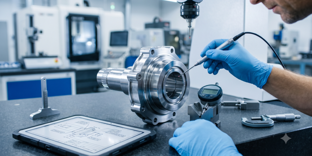
At Merdeka Precision, geometry is not verified by feeling. We use granite tables as reference planes, dial indicators, and bore gauges for roundness and run-out, as well as calibrated measuring tools with clear traceability trails. Every precision component manufacturing job we do is accompanied by a record of measurement results, so you don’t have to take our word for it. You can simply read the data.
This approach to the geometric tolerance of machine components is especially important for customers in the automotive industry sector, where a single component falling out of geometric tolerance can halt an entire assembly line. Measurement data is not an administrative formality. It is proof that your component will behave the same way on the first unit as it does on the five-hundredth unit.
Checklist Before You Order
- Check the Datums: Ensure your drawing explicitly states the datums for the geometric tolerance of the machine components, not just a row of dimensional numbers.
- Ask About Verification Tools: Ask potential partners what tools they use to verify roundness and flatness.
- Request Inspection Reports: Ask for sample inspection reports from previous jobs.
- Discuss Functionality: Discuss the component’s function, not just its shape. A workshop that asks, “where will this component sit?” is usually much safer than a workshop that immediately quotes a price.
Proper understanding of the geometric tolerance of machine components is the language that differentiates between making an object that merely looks similar and making an object that truly works. When a component is made with the correct datums and verified with the right tools, it will fit on the first try, in the hands of whoever installs it. That is one reason why choosing us from the drawing stage is far more cost-effective than calling us after a problem arises.
The True Cost When Geometric Tolerance of Machine Components is Ignored
Geometric tolerance errors in machine components rarely manifest as immediate failures. They appear as unnatural wear, slowly rising oil consumption, vibrations considered normal because the machine is already old, and bearings that wear out ahead of schedule. All these symptoms look like different problems, yet they share a single source: a component whose shape was never right from the day it was installed.
Because the symptoms spread within the geometric tolerance of machine components, the costs also spread out and become difficult to track. You pay in the form of fuel, component replacements, technician work hours, and missed production schedules. When everything is added up after two years, the figure almost always far exceeds the price difference between a correctly made component and one made just to look similar.
Have your engineering drawings correctly applied Geometric Dimensioning and Tolerancing for machine components, or do they still merely state a diameter number? Bring your drawings to our team, and let’s review them together before a single gram of metal is wasted.